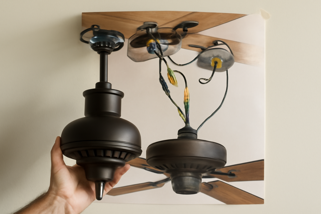
Most homeowners stall on a fan install for one reason: they open the box, unfold the manual, and the printed picture looks like a subway map. A ceiling fan installation diagram is really just three simple systems stacked on top of each other — the mounting box, the bracket-and-downrod, and the wiring — and once you can name each part, the whole job takes a confident afternoon instead of a nervous weekend. I have hung well over a hundred fans, and the mistakes I see are almost never about skill. They are about misreading the picture. This guide walks the diagram the way I read it on the job, part by part and wire by wire.
- What the Diagram Is Actually Showing You
- Start With the Box: Rated vs. Standard
- The Mounting Bracket and Downrod
- Decoding the Wiring Inset
- Making Connections That Last
- Hanging, Canopy, and Blades
- First Power-Up and Wobble Check
- Flush Mount vs. Downrod: Two Different Diagrams
- Common Diagram Mistakes and How to Avoid Them
- Reading the Diagram Like a Pro
What the Diagram Is Actually Showing You
Flip a typical manufacturer diagram sideways and it breaks into a vertical stack. At the top is the electrical box buried in the ceiling. Bolted to that box is the mounting bracket, sometimes called the hanging bracket or J-hook. Below the bracket hangs the downrod (or a low-profile canopy for flush mounts), then the motor housing, and finally the blades and light kit. The exploded view — all those parts floating apart with tiny lines pointing between them — is just showing the assembly order. Read it top to bottom and you have your sequence.
The second half of any good diagram is the wiring inset, usually a small box in the corner with colored lines twisting together. That inset is where people panic, and it is the part I will spend the most time on, because a fan that hangs perfectly but hums or trips a breaker is a callback waiting to happen.
Start With the Box: Rated vs. Standard
No ceiling fan may hang from a standard plastic wiring box. This is the single most important thing the diagram assumes you already know, and it is why fans fall. You need a fan-rated box stamped “Acceptable for fan support,” rated to hold at least 35 pounds for a static fan, and 70 pounds if the diagram shows a heavy fixture. A metal fan-rated box mounted to a brace bar between joists is the gold standard.
If your diagram shows a pancake box (the thin round one), it will also show two long screws going straight up into a joist or brace. Reach up and wiggle the existing box before anything else. If it flexes, stop and replace it — an expandable fan brace bar runs about $18 to $30 and installs through the hole without cutting drywall.
The Mounting Bracket and Downrod
The bracket screws to the box with two heavy machine screws and rubber or nylon washers. Those washers are not optional trim — they dampen vibration, and leaving them off is the number one cause of that maddening low-frequency hum. On the diagram they look like tiny doughnuts; install them.
The downrod carries the fan’s wires down through its center and seats into the motor coupling with a cross pin and cotter pin (or a set screw). Feed the wires through the rod before you pin it — the diagram shows this, but it is easy to miss and miserable to fix afterward. For 8-foot ceilings use the shortest rod, typically 3 to 4 inches, to keep blades at least 7 feet off the floor. For each additional foot of ceiling height, add about 6 inches of downrod so the fan sits 8 to 9 feet up where it moves the most air.
Decoding the Wiring Inset
Here is the color code every U.S. fan diagram uses, and what each wire does:
- Black (fan supply): hot lead for the motor. Connects to the black or red house wire coming from the switch.
- Blue (light kit): hot lead for the light. If you have two switches, blue goes to the red house wire; if one switch, cap blue and black together.
- White (neutral): the fan white joins the house white. Always neutral to neutral.
- Green or bare (ground): the fan ground ties to the house ground and the bracket’s green screw.
Match the diagram to your wall control. Single switch with pull chains: join black and blue from the fan to the single house hot, white to white, ground to ground. Separate wall switches for fan and light: black to black, blue to red, white to white, ground to ground. A fan with a remote receiver changes this — the receiver tucks into the canopy, house hot feeds the receiver’s input, and the receiver’s antenna wire must hang free, not coil around the downrod.
Making Connections That Last
Strip about 5/8 inch of insulation, hold the wire ends parallel and even, and twist a UL-listed wire nut clockwise until the connector bottoms out and the wires twist behind it. Tug each one. A connection that pulls apart in the canopy will arc later. I add a half-wrap of electrical tape on each nut as insurance, then fold the bundle up into the box so the canopy seats flat against the ceiling. Overstuffed canopies push fans off-plumb and cause wobble that looks like a balance problem but is really a wiring problem.
Hanging, Canopy, and Blades
Most brackets have a hook or keyhole slot so the motor hangs while you free both hands to wire. Use it. Once wired, lift the canopy up over the ball or bracket and drive the canopy screws. Only now do you attach blades, using the rubber grommets and the exact screws bagged with each blade iron. Mixing hardware causes the most common wobble. Tighten every blade screw to the housing, then every blade iron to its blade.
First Power-Up and Wobble Check
Restore power at the breaker, not just the wall switch, and test low, medium, and high plus the light. A little startup wobble settles within 60 seconds. If it persists, the fix is almost always mechanical: confirm all blade screws are snug and swap one blade with the one across from it to test for a warped blade. A balance kit — a plastic clip and small weights, included in most boxes — cures the rest. Measure each blade tip to the ceiling; anything more than 1/8 inch of variance points to a bent iron, not a wiring fault.
Flush Mount vs. Downrod: Two Different Diagrams
The diagram in your box will show one of two mounting styles, and mixing them up is a common source of confusion. A downrod diagram shows the motor hanging below a rod and a ball-and-socket canopy — that ball lets the fan self-level on a sloped or vaulted ceiling and is standard for rooms with 9-foot ceilings or higher. A flush-mount (sometimes called “hugger”) diagram skips the downrod entirely and bolts the motor housing tight to a low-profile canopy against the ceiling, which is what you want for rooms under 8 feet where a downrod would drop the blades into head-strike territory.
The wiring is identical between the two — same four colors, same connections — but the mechanical assembly differs, so read the top of the diagram to confirm which style you have before you start. Never install a flush mount on a sloped ceiling; without the ball joint the blades will not sit level and the motor bearings wear out fast. If your ceiling slopes more than about 15 degrees, check that your downrod kit includes a compatible angled mounting adapter, which many diagrams show as a separate optional part.
Common Diagram Mistakes and How to Avoid Them
A handful of misreadings account for nearly every failed install I get called back to fix. The first is skipping the rubber isolation washers between the bracket and box, which the diagram shows as small doughnuts and which prevent the fan’s vibration from transmitting into the structure as a hum. The second is reversing the black and blue leads, which lands you with a fan that runs when you flip the light switch and a light that runs on the fan control. The third is over-tightening blade screws until the iron warps, or under-tightening until they back out and cause wobble.
Two more worth flagging: feeding the wires through the downrod after pinning it, which forces you to disassemble and start over; and forgetting the ground connection to the bracket’s green screw, which the diagram always shows but people skip because the fan runs fine without it right up until a fault makes the housing live. Work slowly through the exploded view, physically touch each part as you find it in the picture, and these mistakes disappear.
Reading the Diagram Like a Pro
When you circle back to the exploded picture with all this in mind, it stops looking like a maze. Top of the stack is the rated box. Under it, the bracket with its rubber washers. Then the downrod carrying wires you fed before pinning. The wiring inset is a four-color conversation: black to hot, blue to light, white to neutral, green to ground. Everything below is mechanical — canopy, motor, blades, balance. A clear ceiling fan installation diagram is not a test of nerve; it is a checklist someone drew in pictures. Work it top to bottom, respect the box rating, honor the color code, and you will hang a fan that runs cool, quiet, and dead level for the next 20 years. If any part of the wiring leaves you guessing, a licensed electrician will run the connections in under an hour, and there is no shame in buying certainty on the one part of the job that can burn a house down.