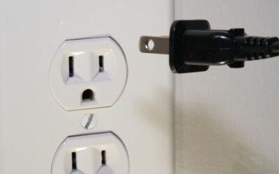
Replacing or adding an electrical outlet is one of the most common home wiring tasks, yet mistakes here cause thousands of house fires every year. Wiring an outlet correctly requires understanding circuit basics, using the right materials, and following the National Electrical Code. The actual hands-on work takes under 15 minutes per outlet once you know the process, and the materials cost less than $5.
Tools and Materials You Need
Gather everything before you start. Opening up a live electrical box without the right tools puts you at risk of shock or a poor connection that fails later.
- Non-contact voltage tester (essential safety tool, $15-$25)
- Wire strippers rated for 14 and 12 AWG
- Flat and Phillips screwdrivers
- Needle-nose pliers
- New receptacle: 15A for #14 wire on a 15A circuit, 20A for #12 wire on a 20A circuit
- Electrical tape
- Wire nuts (yellow for #14, red for #12 bundles)
Never use a 15A receptacle on a 20A circuit with #12 wire. The receptacle’s lower rating becomes the weak link and can overheat under load. Match the receptacle amp rating to the circuit breaker and wire gauge.
Turn Off Power and Verify
Go to your electrical panel and switch off the breaker for the circuit you will be working on. Then use a non-contact voltage tester at the outlet to confirm the power is dead. Test both slots of the receptacle and the ground hole. If you have any doubt about which breaker controls the outlet, turn off the main breaker.
Voltage testers cost as little as $15 and are non-negotiable for any electrical work. Professional electricians test at every box they open, every single time. Follow that habit.
Understanding the Wires
A standard residential outlet box contains three wires inside a Romex (NM-B) cable:
- Black (hot): Carries 120V from the breaker panel
- White (neutral): Returns current to the panel
- Bare or green (ground): Safety path for fault current
In a “middle of run” box, you will find two cables entering the box: one feeding power from upstream and one continuing downstream to the next outlet. This means two black wires, two white wires, and two ground wires inside the box.
Wiring a Standard 15A or 20A Outlet
Strip about 3/4 inch of insulation from each wire end. Use the strip gauge on the side of the receptacle as a reference since most receptacles have a marking showing the exact length.
- Connect the ground wire first. Bend the bare copper into a clockwise hook around the green ground screw on the receptacle. Tighten firmly. If two ground wires are present, pigtail them with a short piece of bare wire using a wire nut, then connect the pigtail to the screw
- Connect the white (neutral) wires to the silver-colored screws on the receptacle. For middle-of-run boxes, use both silver screws or pigtail with a wire nut
- Connect the black (hot) wires to the brass-colored screws. Same approach: use both screws or pigtail
- Wrap electrical tape around the receptacle body, covering the terminal screws as an extra layer of insulation
- Carefully fold the wires back into the box, push the receptacle in, and secure it with the mounting screws. Do not force wires; make neat folds
- Install the cover plate and restore power at the breaker
Screw Terminals vs Backstab Connections
Many outlets have small holes in the back for “backstab” or push-in connections. These are fast but unreliable. The spring-loaded contacts inside loosen over time and cause arcing. Always use the screw terminals for a secure, long-lasting connection. Wiring an outlet with screw terminals takes only a few extra seconds and is vastly more reliable.
Wiring a GFCI Outlet
GFCI (Ground Fault Circuit Interrupter) outlets are required by code in kitchens, bathrooms, garages, outdoor locations, and anywhere within 6 feet of a water source. They have two sets of terminals marked LINE and LOAD.
Connect the incoming power cable to the LINE terminals: black to brass, white to silver. If you want the GFCI to protect downstream outlets as well, connect the outgoing cable to the LOAD terminals. If the outlet is the only one on the circuit or you want protection only at this location, cap the LOAD terminals with the sticker provided and leave them unused.
After installation, press the TEST button. The outlet should trip immediately, cutting power. Press RESET to restore it. If the GFCI will not trip on test, the wiring is incorrect or the device is defective.
Code Requirements to Know
The NEC sets minimum standards for outlet wiring that local inspectors enforce. Key rules that affect DIY work:
- Outlets must be tamper-resistant (TR) in all new residential installations as of NEC 2008
- Box fill calculations limit how many wires can occupy a junction box. A standard 18 cu in old-work box handles two cables (6 wires plus grounds) comfortably
- Maximum of one receptacle per “yoke” on a dedicated 20A circuit (like kitchen countertop circuits)
- Ground wires must be connected even if the original box had no ground. Retrofit grounding with a GFCI is an acceptable alternative in older homes
- All wire splices must be inside a covered, accessible junction box. Never bury a splice in a wall
Testing Your Work
After restoring power, use an outlet tester ($8-$15 at any hardware store) to verify correct wiring. These plug-in testers have three indicator lights that reveal open grounds, reversed polarity, and open neutrals at a glance. A correct reading shows two amber lights (or whatever the tester’s manual specifies for “correct”). Any other combination indicates a wiring error that must be fixed before using the outlet.
Taking 15 minutes to wire an outlet properly protects your family and your home. If you encounter unexpected wiring, aluminum conductors, or boxes with more than two cables, consult a licensed electrician rather than guessing. Some complexity is worth paying a professional to handle safely.