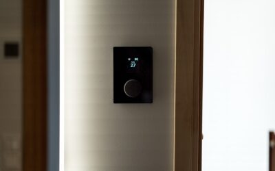
If you have ever opened an LED panel, troffer or high-bay fixture and found two extra thin wires, one purple and one gray, you were looking at a dimming input that a regular wall dimmer cannot control. Those wires belong to a 0-10V dimmer switch system, a method that dims LEDs by sending a small control signal to the fixture’s driver instead of chopping up the power going to the light. It is the standard in commercial buildings and it is showing up more in homes with modern LED fixtures, garage shop lights and wafer downlights.
In short: the dimmer still switches line voltage on and off, but brightness is set through a separate low-voltage pair of wires. At 10 volts on that pair the light runs at full output. As the signal drops toward 1 volt or 0 volts, the driver dims the LEDs. The driver does the real work, so the fixture must have a 0-10V dimmable driver for any of this to function.
- What a 0-10V Dimmer Switch Does
- Which LED Fixtures Need 0-10V Dimming
- 0-10V vs Phase Dimmers
- Low-Voltage vs Line-Voltage Wiring Basics
- Tools and Materials
- How a 0-10V Dimmer Is Wired: Step-by-Step Overview
- Setting Low-End Trim and Range
- Troubleshooting Common Problems
- Typical Costs
- When to Call a Licensed Professional
- Frequently Asked Questions
Understanding how the two circuits work together, which fixtures need this type of control, and when to call an electrician will save you from flicker, buzzing and returns.
What a 0-10V Dimmer Switch Does
A standard household dimmer is a phase-cut dimmer. It sits in series with the light and trims part of each AC wave, so the fixture receives less power and gets dimmer. That works fine for incandescent bulbs and many screw-in LED bulbs, but larger LED fixtures with separate drivers often do not respond well to phase dimming.
A 0-10V dimmer switch splits the job in two:
- Line-voltage side (120V or 277V): the switch turns power to the fixture fully on or fully off through a normal hot, neutral and ground connection. In most models this side does not dim at all; it only switches.
- Low-voltage control side: two small conductors, usually purple (positive, often labeled DIM+) and gray (negative, DIM-), run from the dimmer to the driver. The driver reads the signal on that pair and sets LED output to match.
Because the dimming happens inside the driver, the light receives clean, full power all the time. That is why a 0-10V LED dimmer setup tends to dim more smoothly, with less flicker and less audible buzz, than phase dimming on the same fixture.
Sinking vs sourcing
Most residential and commercial drivers are “current sourcing,” meaning the driver itself supplies the small control current and the dimmer simply pulls the signal down to dim. The dimmer in that arrangement is “current sinking.” Mismatching a sourcing control with a sourcing driver is a common reason a system will not dim, so check that the dimmer specifications say it works with sourcing drivers, which covers the vast majority.
Which LED Fixtures Need 0-10V Dimming
Look at the fixture label or spec sheet. If it lists “0-10V dimming” or shows purple and gray leads, it is designed for this type of control. Common examples:
- LED flat panels and troffers in basements, offices and finished garages
- Linear LED shop lights and strip fixtures with integral drivers
- High-bay and low-bay lights in workshops and pole barns
- Some commercial-style recessed downlights and wafer lights
- Many LED tape light systems that use a separate 0-10V dimmable driver
- Outdoor wall packs and area lights with dimming options
Screw-in LED bulbs never use 0-10V. They have no separate control wires and need a phase dimmer rated for LED loads. If your fixture has only black, white and ground wires and no purple or gray, a 0-10V dimmer switch will turn it on and off but will not dim it.
0-10V vs Phase Dimmers
| Feature | 0-10V dimming | Phase dimming (forward or reverse) |
|---|---|---|
| How it dims | Low-voltage signal to the driver | Trims the AC power waveform |
| Extra wires | Purple and gray control pair | None |
| Typical fixtures | Panels, troffers, high-bays, drivers | Screw-in bulbs, many residential fixtures |
| Flicker and buzz | Usually low | Depends on bulb and dimmer match |
| Fixtures per dimmer | Many, limited by switch relay and control rating | Limited by dimmer wattage rating |
Neither method is better in every case. The right choice is the one the fixture’s driver was designed for. Some drivers accept both phase and 0-10V input, which gives you flexibility, but you must pick one control method and wire for it.
A related point: a 0-10V dimmer switch does not lower power draw in the same direct way a phase dimmer feels like it does, yet the LEDs do use less energy when dimmed because the driver reduces output. The savings show up on the bill just the same.
Low-Voltage vs Line-Voltage Wiring Basics
This is the part that trips up most DIY projects. The control wires carry a small low-voltage signal, typically treated as Class 2 wiring. The supply wires carry full line voltage. Code generally requires the two to be kept separated or insulated for the higher voltage where they share a box or conduit. Many fixtures run the purple and gray leads through the same compartment as line voltage, which is allowed only when the conductor insulation is rated for it, so follow the fixture instructions and local code exactly.
When a new 0-10V system is installed, the run between the dimmer and each fixture usually needs a cable that includes two extra conductors for the control pair, or a separate low-voltage cable routed according to code. In an existing house where only a standard two-wire cable runs to the light, adding the control pair can mean fishing new cable through walls and ceilings. That is a strong reason to have an electrician handle the job.
Tools and Materials
- 0-10V dimmer switch rated for your line voltage and load
- 0-10V dimmable LED fixtures or drivers
- Non-contact voltage tester
- Screwdrivers, wire strippers and lineman’s pliers
- Listed wire connectors sized for the conductors
- Cable with control conductors or approved low-voltage cable
- Deep wall box if the dimmer body is large
- Wallplate that fits the dimmer style
How a 0-10V Dimmer Is Wired: Step-by-Step Overview
The steps describe a typical replacement where the control wires already run between the box and the fixture. New circuits, new switch locations and any added cable runs belong to a licensed electrician.
- Turn off the breaker. Switch off the circuit at the panel, then confirm power is off at the switch box and fixture with a non-contact voltage tester. Never work on energized wires or try to test a live circuit.
- Identify the wires. At the switch box you should find the line (hot) feed, the switched leg to the fixture, a neutral if the dimmer needs one, ground, and the purple and gray control pair heading to the light.
- Read the dimmer instructions. Most units have black leads for line and load, a white neutral lead on models that need it, a green ground and separate purple and gray low-voltage leads.
- Connect ground and neutral first. Ground to the bare or green conductor, neutral to the bundle of white neutrals if required.
- Connect line and load. Join the dimmer’s line lead to the incoming hot and the load lead to the switched conductor going to the fixture.
- Connect the control pair. Purple to purple (DIM+) and gray to gray (DIM-). Reversing them usually means the light stays at full or minimum brightness.
- Check the fixture end. At the fixture the driver’s purple and gray leads connect to the same pair. Keep low-voltage connections separated from line voltage as the fixture instructions show.
- Fold, mount and restore power. Tuck the wires neatly, mount the dimmer, install the plate and turn the breaker back on. Run the dimmer through its full range to see that it reaches full brightness and dims smoothly.
Setting Low-End Trim and Range
Many dimmers include a small trim adjustment for the bottom of the dimming range. Drivers differ in how low they will go; some dim to 10 percent, others to 1 percent or close to off. If the light flickers or drops out at the bottom, raise the low-end trim until it holds steady. Some dimmers also offer a “dim to off” behavior, but many drivers never reach true zero output, which is why the line-voltage relay inside the switch handles the actual off function.
Troubleshooting Common Problems
- Light turns on and off but will not dim: the fixture may not have a 0-10V driver, the control pair may be disconnected, or purple and gray may be reversed.
- Light stays dim and never reaches full: a broken or shorted control wire often pins the signal low. Check connections with the power off.
- Flicker at low levels: raise the low-end trim, and confirm all drivers on the circuit are the same type.
- Some fixtures dim, others do not: mixed drivers or a missed control connection at one fixture.
- Dimmer runs warm: make sure the total load stays within the switch rating and that the wallbox is not overstuffed. Ganged dimmers may need derating per the instructions.
- Buzzing: usually from the fixture, not the switch. A 0-10V system should be quiet; buzz may point to a loose connection or failing driver.
Do any inspection with the breaker off. If the problem is not a simple loose or swapped connection, have an electrician diagnose it.
Typical Costs
A residential-style 0-10V control generally costs a bit more than a basic phase dimmer, usually in the range of a few tens of dollars, with smart or multi-location versions costing more. 0-10V dimmable LED fixtures run from budget shop lights to premium panels. Labor varies most: swapping a dimmer where the control wires already exist is a short service call, while adding control wiring to existing finished ceilings can run into several hundred dollars or more depending on access.
When to Call a Licensed Professional
Hire a licensed electrician for any new circuit, new switch location, added cable run or work in a commercial-style panel. The same goes for 277V lighting, which is common in commercial spaces and some large shops, and for multi-location or zoned control systems. Most areas require permits for new lighting circuits, and an electrician will know how your local code treats Class 2 control wiring in shared boxes. If you are not sure whether the circuit is off, or the wiring in the box does not match what you expect, stop and call a pro.
For a homeowner, the main takeaway is simple: match the dimmer to fixtures with 0-10V drivers, keep low-voltage and line-voltage wiring handled correctly, and never work with the power on.
Frequently Asked Questions
What are the purple and gray wires on an LED fixture?
They are the 0-10V dimming control pair. Purple is DIM+ and gray is DIM-. They connect to the matching leads on a 0-10V dimmer so the driver can set brightness. If you are not using dimming, follow the fixture instructions, which usually say to cap them separately.
Can I use a regular dimmer on a 0-10V fixture?
Usually not. A standard phase dimmer is not designed for most 0-10V drivers and can cause flicker, buzzing or no dimming at all. Some drivers accept both methods, so check the fixture label before choosing a control.
Does a 0-10V dimmer need a neutral wire?
Many models do, especially those with electronic relays or smart features. Check the product instructions and the wall box before buying. If no neutral is present, an electrician can advise on options.
How many fixtures can one 0-10V dimmer switch control?
It depends on two ratings: the line-voltage relay load in watts or amps and the control current limit for the number of drivers. Add up the fixtures and stay within both ratings with some headroom.
Is 0-10V dimming better than phase dimming?
Neither is universally better. A 0-10V LED dimmer setup often dims more smoothly on fixtures built for it, while phase dimming is simpler for screw-in bulbs and basic fixtures. Use the method your fixture’s driver supports.