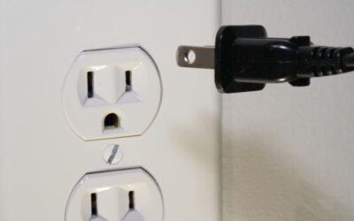
Swapping a dead outlet is one of the most common DIY projects, and also the one most likely to cause a house fire if done wrong. Knowing how to wire an electrical outlet correctly comes down to three fundamentals: kill the power and verify it is off, match wires to the right terminals, and use screw terminals rather than the back-stab push-in holes. Miss any of these and you end up with intermittent power, overheated wires, or a tripped arc-fault breaker that will not reset. This guide walks through a standard 15-amp or 20-amp duplex receptacle swap from start to finish.
- Safety First: Kill the Power and Verify
- Tools and Materials You Need
- Identifying the Wires
- Matching Wires to Terminals
- Side-Wire (Screw) vs Back-Wire (Push-In) Connection
- Step-by-Step Wiring Process
- Pigtailing Grounds and Multiple Connections
- Wiring a GFCI Outlet Correctly
- Common Mistakes and Fixes
- When to Call an Electrician
Safety First: Kill the Power and Verify
Before touching anything, turn off the breaker feeding the outlet. Do not trust the breaker label; it is often wrong in older houses. Plug a lamp or tester into the outlet to confirm it is dead, or use a non-contact voltage tester against the face of the outlet.
Pull the outlet forward slightly after removing the cover plate and check both sets of screws with the tester again. Some outlets are wired on two different circuits (especially kitchen counter receptacles with split-tabs), so one breaker trip may not kill the whole box. Treat every wire as hot until your tester proves otherwise.
Tools and Materials You Need
A basic outlet swap requires:
- Non-contact voltage tester ($15)
- Flathead and Phillips screwdrivers
- Needle-nose pliers
- Wire strippers rated for 12 and 14 AWG
- New duplex receptacle ($1.50 for builder-grade, $3 for TR spec-grade, $20-$40 for GFCI or AFCI)
- Electrical tape
- Outlet plug-in tester ($10) to verify correct wiring after
Match the receptacle rating to the circuit. A 15-amp circuit (14-gauge wire) gets a 15-amp receptacle; a 20-amp circuit (12-gauge wire) gets a 20-amp receptacle with the horizontal T-slot neutral.
Identifying the Wires
Residential outlets are fed with three wires in a standard NM cable (Romex):
- Hot: Black (or red on a secondary circuit). Carries 120V from the breaker.
- Neutral: White. Returns current to the panel at 0V.
- Ground: Bare copper or green insulated. Safety path to earth.
A middle-of-run outlet has two cables: one feeding in and one continuing to the next device. That means you will have two black wires, two white wires, and two bare coppers in the box. An end-of-run outlet has only one of each.
Matching Wires to Terminals
Every standard duplex receptacle has the same terminal layout:
- Two brass screws on one side for hot (black)
- Two silver screws on the other side for neutral (white)
- One green screw at the top or bottom for ground
The two brass screws are connected internally by a small break-off tab, as are the two silver screws. This lets a single hot and single neutral wire power both outlet slots. Break the tab only if you want to wire each half of the receptacle to a different circuit or switch.
Side-Wire (Screw) vs Back-Wire (Push-In) Connection
Receptacles have two connection methods. Push-in back-stab holes are quick but use a small spring contact that loosens over years of thermal expansion. Side-wire screw terminals clamp the wire firmly and are what electricians use almost exclusively.
Always use the screw terminals. Loop the wire clockwise around the screw using needle-nose pliers so tightening the screw pulls the loop tight. If the receptacle has back-clamp terminals (where the screw compresses a plate rather than a push-in contact), that option is also fine; it uses the screw to secure the straight wire against a plate.
Step-by-Step Wiring Process
Assuming a middle-of-run outlet with two cables, follow these steps:
- Confirm power is off. Test again with your non-contact tester.
- Unscrew the old receptacle from the box and pull it forward carefully.
- Note how the existing wires are connected before removing them. Photograph with your phone.
- Loosen each terminal screw and remove the wires from the old receptacle.
- Straighten the wires and check for damage. Strip a fresh 3/4-inch of insulation if the old ends are nicked.
- On the new receptacle, connect the two bare copper grounds by pigtailing them to a 6-inch piece of bare copper, then connect that pigtail to the green screw. Alternatively, wire each ground under its own green screw position if the receptacle has dual grounds.
- Connect the black hot wires to the two brass screws. If you have only one hot (end-of-run), connect it to either brass screw.
- Connect the white neutrals to the two silver screws.
- Tighten each screw until snug (about 12 in-lbs for #10 screws).
- Wrap the body of the receptacle with a wrap of electrical tape over the terminals for added insulation.
- Fold the wires neatly back into the box and push the receptacle into place.
- Secure with the two mounting screws through the yoke into the box.
- Reinstall the cover plate.
- Turn the breaker back on and test with a plug-in outlet tester. The tester should show correct wiring (typically two yellow LEDs on a 3-light tester).
Pigtailing Grounds and Multiple Connections
When you have more than two wires of the same type, pigtailing is the safest approach. For example, three black hot wires should not all be jammed under two brass screws. Instead, twist the three together with a 6-inch piece of the same gauge wire, cap with a yellow wire nut, and connect only the free pigtail end to the brass screw.
Pigtailing is code-compliant per NEC 300.13(B) for neutrals on multi-wire circuits and is good practice for hots and grounds anywhere more than one wire meets.
Wiring a GFCI Outlet Correctly
GFCI receptacles have two sets of terminals labeled LINE and LOAD. LINE is where the power comes from the panel; LOAD sends power downstream to other outlets you want to protect. If you reverse these, the GFCI will not reset. The receptacle ships with a yellow tape over the LOAD terminals as a reminder; do not use those unless you are extending protection to downstream outlets.
After installing, press the TEST button. The RESET button should pop out and kill power. Press RESET to restore. A working GFCI trips within 40 milliseconds on a fault.
Common Mistakes and Fixes
Issues that show up after a DIY outlet swap:
- Outlet has no power: Breaker not reset, or hot/neutral reversed. Turn off and recheck wiring.
- Outlet works but tripping breaker: Ground touching a hot terminal, or too many devices on the circuit.
- Tester shows open ground: Ground wire not connected or the box is ungrounded. Pigtail to the metal box if the box itself is grounded.
- Hot-neutral reverse: Swap the black and white at the terminals.
- Arc fault trips: AFCI breaker is sensing an issue. Recheck all connections; loose screws are a common cause.
When to Call an Electrician
Stop and call a licensed electrician if you find aluminum wiring (dull silver instead of copper), cloth-insulated knob-and-tube wiring, more than six conductors in a shallow box, or any burnt insulation. These situations require experience and often permits that a homeowner should not DIY. A service call for an outlet fix typically runs $120 to $250 and is money well spent if the wiring looks older than 1970.