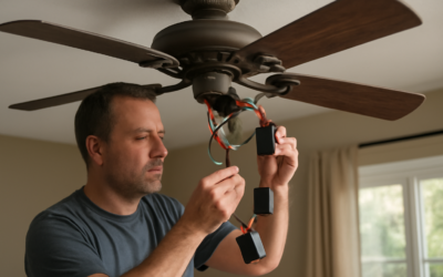
If your ceiling fan runs on only one speed, hums but will not start, or lost its slow setting entirely, the problem almost always traces back to one small component. The 3 wire ceiling fan connection with capacitor is the standard wiring arrangement inside most pull-chain and wall-controlled fans, and the capacitor is the part that makes multiple speeds possible. Understanding how these three wires and the capacitor work together lets you diagnose a dead speed setting and replace a $6 part instead of the whole fan.
Why a Ceiling Fan Needs a Capacitor
A single-phase AC motor cannot easily change speed on its own. To create low, medium, and high settings, fan manufacturers wire a capacitor into the circuit. The capacitor stores and releases electrical energy, shifting the phase of the current fed to the motor’s start winding. By routing power through different sections of the capacitor, the fan draws different amounts of current and spins at different speeds. Without the capacitor, the motor would run at only one speed, or fail to start at all, humming while it sits still.
What the Three Wires Actually Do
In a typical 3-speed fan, the capacitor has three output wires plus the incoming line. Each wire corresponds to a speed tap. The common color scheme, though it varies by brand, looks like this:
- Line (usually purple or the incoming hot): Feeds power into the capacitor and the speed switch.
- High speed: Often connects most directly to the motor winding for maximum current.
- Medium speed: Routes through part of the capacitor for reduced current.
- Low speed: Routes through the full capacitor value for the lowest current and slowest spin.
The pull chain or wall control simply selects which of these three wires connects to the motor at any moment. The printed capacitor value, such as “CBB61 1.2uF + 2.5uF + 3.5uF,” tells you the microfarad rating of each internal section, and matching those numbers is critical when replacing the part.
How the Speed Switch Ties It Together
The pull-chain switch inside the fan housing is a rotary selector with four positions: off, high, medium, and low. Each pull advances it to the next tap. Power comes in on the line wire, passes through the switch, and exits on whichever speed wire the switch has selected. That wire carries the current through the appropriate capacitor section and on to the motor. This is why a bad switch and a bad capacitor produce similar symptoms; both interrupt the path to one or more speeds.
Diagnosing a Failed Capacitor
A dead capacitor is the most common ceiling fan failure. Watch for these telltale signs:
- The fan only works on one speed, usually high, while other settings do nothing.
- The fan hums but the blades will not start turning until you spin them by hand.
- The fan runs slowly on every setting, with no real difference between them.
- You notice a faint burning smell or see a swollen, cracked, or leaking capacitor when you open the housing.
Because the capacitor sits in a small black or silver box near the switch, a visual inspection often confirms the diagnosis. A bulging case or brown scorch marks mean it is finished.
Replacing the Capacitor Safely
This is a manageable repair, but it involves line-voltage wiring, so treat it with care.
- Cut the power. Turn off the breaker feeding the fan, not just the wall switch, and confirm it is dead with a voltage tester.
- Access the switch housing. Remove the light kit or the bottom cap to reach the wiring and the capacitor.
- Photograph the connections. Note exactly which capacitor wire ties to which fan wire before disconnecting anything.
- Match the replacement. Buy a capacitor with the identical microfarad values and the same number of wires. A CBB61 rated for your fan’s uF numbers is the standard replacement.
- Transfer the wires. Connect the new capacitor exactly as the old one was wired, using the correct wire connectors.
- Reassemble and test. Close the housing, restore power, and cycle through all speeds.
Getting the Capacitor Rating Right
The single most important detail is matching the microfarad values. A capacitor with the wrong rating will run the fan at incorrect speeds, overheat, or fail quickly. The values are printed on the old capacitor’s label; a common three-speed rating is “1.2uF + 2.5uF + 3.5uF” combined in one CBB61 package. If the original label is unreadable, look up your fan model or count the wires and buy a matching multi-value capacitor. Never substitute a single-value capacitor for a multi-value one, because you will lose your speed settings.
When It Is Not the Capacitor
If a new capacitor does not fix the problem, suspect the pull-chain switch next. Switches wear out from thousands of pulls and can fail to connect certain taps. A cheap replacement switch, matched to the number of wires on the original, usually solves a fan that still misbehaves after a capacitor swap. Only after both the capacitor and switch check out should you suspect the motor windings themselves, at which point replacing the fan is usually the smarter economic choice.
Final Thoughts
The 3 wire ceiling fan connection with capacitor is simpler than it looks once you see how the three speed wires route current through different sections of the capacitor. A fan stuck on one speed or humming without spinning is nearly always a $6 capacitor away from working like new. Cut the power, photograph the wiring, match the microfarad values exactly, and you can bring a “broken” fan back to full three-speed operation in under an hour.