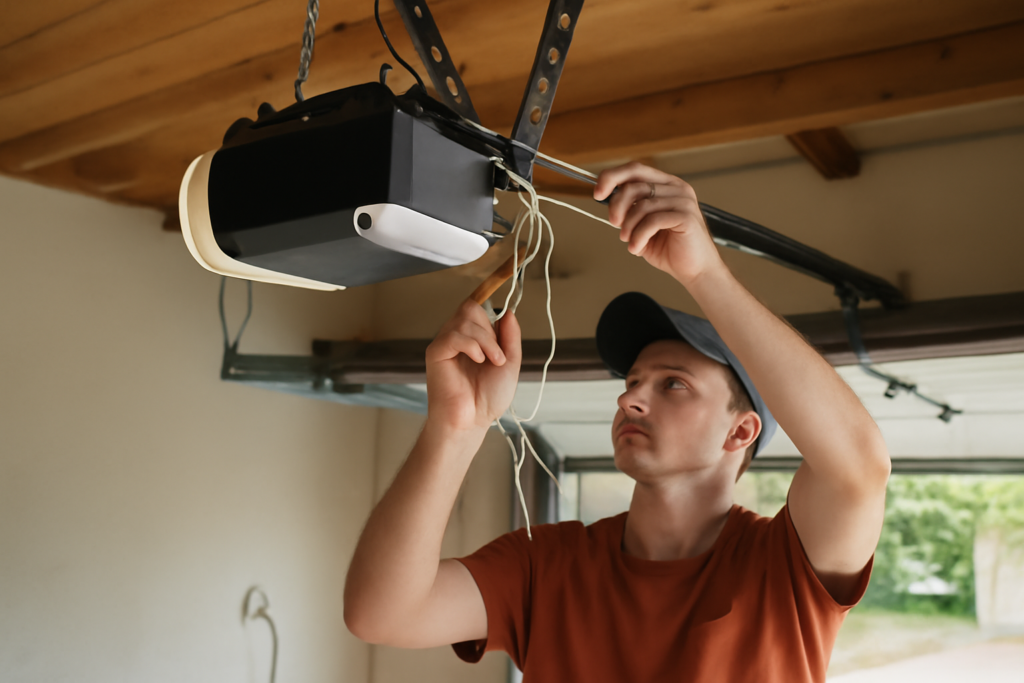
Here’s the good news that surprises most first-timers: the low-voltage wiring on a garage door opener is genuinely beginner-friendly. Learning how to wire a garage door opener mostly means connecting two thin wires to a handful of terminals — the wall button, the pair of photo-eye safety sensors, and the antenna — none of which will shock you because they run on harmless low voltage. The only truly electrical part is plugging the unit into a standard outlet. Get the low-voltage connections right and the door opens smoothly and stops safely; get a sensor wire crossed and the door simply won’t close until you fix it. This guide walks through every connection in plain terms.
Part of our Garage Doors guide — explore the full guide →
- Understanding the Two Types of Wiring
- Tools and Materials
- Wiring the Wall Control Button
- Wiring the Safety Sensors (Photo Eyes)
- The Antenna and Power
- Testing and the Force/Travel Settings
- Troubleshooting Common Wiring Problems
- Understanding the Wire and Terminal Basics
- Upgrading and Adding Accessories
- Final Word
Understanding the Two Types of Wiring
A garage door opener has two separate electrical systems, and keeping them straight prevents most confusion:
- Line voltage (120V): the standard household power that runs the motor. On nearly every residential opener, this is just a three-prong plug that goes into a ceiling outlet — no hardwiring, no shock risk if you use the plug as intended.
- Low voltage (typically 24V or less): the thin bell wire connecting the wall control button and the two safety sensors to the motor unit’s terminals. This is the wiring you’ll actually be running, and it’s completely safe to handle.
Because the low-voltage side won’t shock you, you can work on those connections without cutting power. Still, unplug the unit before doing anything near the motor head, just for good practice.
Tools and Materials
- Low-voltage bell wire (usually included with the opener; 18-to-22-gauge two-conductor)
- Wire strippers and a small flathead screwdriver
- Wire staples or insulated cable clips
- Ladder and a stud finder
- The opener’s manual — terminal layouts vary by brand
Keep the manual handy. LiftMaster, Chamberlain, Genie, and others label their terminals slightly differently, and the manual’s diagram is the fastest way to match wire to terminal.
Wiring the Wall Control Button
Start with the wall button, mounted where you can see the door but out of a child’s easy reach, at least 5 feet up. Run two-conductor low-voltage wire from the button location up to the motor unit.
- Strip about half an inch of insulation from both wire ends.
- Connect the two wires to the two screw terminals on the back of the wall button — polarity usually doesn’t matter for a basic button.
- Route the wire up the wall and across the ceiling to the motor head, stapling it neatly every few feet. Take care not to pierce the wire with a staple, which causes a short.
- Connect the other ends to the terminals marked for the wall control or push-button on the motor unit.
Once connected, plug in the opener and press the button — the motor should run. If nothing happens, recheck that both wires are seated under their terminal screws and that no staple has crushed the wire.
Wiring the Safety Sensors (Photo Eyes)
The two photo-eye sensors are the most important safety feature on the opener and, not coincidentally, the most common source of wiring headaches. They mount near the floor on each side of the door, no higher than 6 inches, and shine an invisible beam across the opening. Break that beam — a foot, a pet, a bike — and the door refuses to close.
- Mount both sensors facing each other at the same low height on the door tracks or wall brackets.
- Run bell wire from each sensor back to the motor unit.
- Observe polarity here — sensor wiring often has a white/black or striped/solid convention. Match the striped or white conductor to the correct labeled terminal on both the sensors and the motor unit.
- Connect to the sensor terminals on the motor head.
When wired correctly, both sensors show a steady indicator light. A blinking or dark sensor LED means the beam is misaligned or the wires are reversed. Aligning the two sensors so their lights stay solid is the step that trips people up most — nudge them until both glow steadily.
The Antenna and Power
Most openers have a short antenna wire hanging from the motor head that improves remote range — just let it dangle straight down, don’t coil or cut it. Finally, plug the unit into the ceiling outlet. If there’s no dedicated outlet, have a licensed electrician add one; never run the motor from an extension cord as a permanent solution.
Testing and the Force/Travel Settings
With everything wired and powered, run through the safety checks:
- Test the wall button — the door should open and close fully.
- Test the sensors — wave a broom through the beam while the door closes; it must reverse immediately.
- Test auto-reverse — place a 2×4 flat on the floor under the door; the door should reverse when it contacts the board.
- Set the travel and force limits per the manual so the door fully opens and closes without straining or leaving a gap.
The safety reversal tests are non-negotiable. An opener that doesn’t reverse on an obstruction is dangerous, so don’t skip these before you consider the job done.
Troubleshooting Common Wiring Problems
- Door won’t close, opener light blinks: almost always a sensor issue — misaligned, reversed wires, or a pinched wire.
- Nothing happens on button press: loose or crossed wall-button wire, or a staple shorting the run.
- Intermittent operation: a wire pierced by a staple making poor contact.
- Short remote range: antenna coiled or tucked up instead of hanging free.
Understanding the Wire and Terminal Basics
A little background makes the whole job clearer. The low-voltage wire used for the button and sensors is thin two-conductor wire, commonly 18 to 22 gauge, often called bell wire or thermostat wire. It usually comes bonded as a pair with a small ridge or stripe on one conductor so you can tell the two apart — that marking is how you keep polarity consistent on the sensor circuit.
The motor unit has a row of small screw or push-in terminals, and the manual maps each one: a pair for the wall control, a pair for the safety sensors, and sometimes terminals for accessories. When you strip the wire, expose about half an inch of copper, twist the strands together so no whiskers stray, and seat them fully under the terminal. A loose strand touching an adjacent terminal is a classic cause of erratic behavior, so keep the connections clean and tight.
Upgrading and Adding Accessories
Once the basics are wired, the same low-voltage approach lets you add convenient accessories, most of which connect to the same terminals or pair wirelessly:
- A wired keypad for entry without a remote — some hardwire to the wall-button terminals, though many are now wireless.
- Additional wall consoles in a second location, wired in parallel to the first.
- A second set of safety sensors on very wide or tandem doors.
- Smart-home modules that let you open the door from a phone app; these typically tie into the wall-button terminals.
When adding a wired accessory, always disconnect power at the plug first, follow the accessory’s terminal diagram, and keep the runs neat and stapled clear of moving parts. Because everything runs on the same harmless low voltage, expanding your system later is well within DIY reach — the skills are identical to the original wiring job.
Final Word
Knowing how to wire a garage door opener is well within reach for any homeowner willing to follow the terminal diagram in the manual. The wiring is low-voltage and safe to handle, the connections are just a few screw terminals, and the trickiest part — aligning the safety sensors until their lights hold steady — takes patience, not expertise. Wire the button, wire the photo eyes with correct polarity, plug it in, and run the safety tests. Do that carefully and you’ll have a door that opens on command and, more importantly, stops safely every single time.