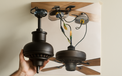

When a fan wobbles, won’t start, or the light quits, most people stare up at it with no idea what they are looking at. A clear ceiling fan diagram demystifies the whole assembly, showing how the motor, blades, mounting bracket, and wiring connect so you can install a new fan or troubleshoot an old one without guesswork. Understanding the parts and their relationships is the difference between confidently swapping a pull chain and calling an electrician for a five-dollar fix. This guide walks through every component from ceiling to blade tip, explains the wiring color code, and shows how it all fits together.
The Main Components, Top to Bottom
A ceiling fan is a stack of parts that transfer from the electrical box in your ceiling down to the spinning blades. Picture the diagram as a vertical assembly with these pieces in order:
- Mounting bracket: The metal plate that screws to the ceiling electrical box and holds the fan’s weight.
- Downrod: The pipe that hangs the motor below the ceiling, sized for ceiling height.
- Canopy: The decorative cover that hides the bracket and wiring at the ceiling.
- Motor housing: The central body containing the motor that spins the blades.
- Blade irons (arms) and blades: The brackets that bolt blades to the motor at a pitched angle.
- Switch housing: The lower cap holding the reverse switch and pull chains.
- Light kit: The optional lamp assembly that bolts to the bottom of the motor.
Every fan follows this basic stack whether it is a budget builder model or a designer fan, so once you understand the sequence, you can service almost any unit.
The Mounting System
Everything hangs from the mounting bracket, which must attach to a fan-rated electrical box, not a standard lightweight box. A fan-rated box is anchored to a joist or a listed brace bar so it can carry the fan’s weight and the dynamic load of spinning blades. Using a regular box is the leading cause of fans falling from the ceiling.
The bracket often includes a rubber isolation grommet or a ball-and-socket mount at the top of the downrod, which lets the fan hang plumb and dampens vibration. On the diagram, note how the downrod’s ball drops into the bracket’s cradle, letting the fan self-level. A hanging hook on the bracket holds the motor while you connect the wires, freeing your hands during installation.
Understanding the Downrod and Canopy
The downrod sets how far the fan hangs below the ceiling, and getting it right matters for both safety and performance. Fan blades should sit at least 7 feet above the floor and ideally 8 to 9 feet for best airflow, with blade tips kept at least 18 inches from any wall. On a standard 8-foot ceiling, a short 3 to 6 inch downrod or a flush-mount hugger fan works; on a vaulted or 10-foot ceiling, a longer 12 to 36 inch downrod drops the fan into the effective zone.
The canopy slides up the downrod to cover the bracket and the wire connections once everything is joined. On sloped ceilings, an angled canopy or a special mount keeps the fan hanging vertically. The downrod carries the motor wires down through its hollow center to the motor housing below.
The Wiring Diagram Explained
The wiring is where a diagram earns its keep. A standard fan with a light has these wires, and matching them correctly is straightforward once you know the color code:
- Black: Hot wire for the fan motor.
- Blue: Hot wire for the light kit.
- White: Neutral, shared by motor and light.
- Green or bare copper: Ground, connected to the bracket and the fan’s ground.
In the ceiling box you will typically find a black (or sometimes red) supply hot, a white neutral, and a ground. Connect white to white, ground to ground, and then the supply hot to the fan wires. With a single switch controlling both, join the supply hot to both the fan’s black and the light’s blue. With separate switches, the black supply feeds the fan black and a red supply wire feeds the blue light wire, giving independent control. Always cap connections with wire nuts and cut power at the breaker before touching any wire.
The Motor and Blade Assembly
The motor is the heart of the fan, and its type affects how it runs. Traditional AC motors are simple and reliable, while newer DC motors are quieter, use less energy, and offer more speed settings, often with a remote. Inside the switch housing sits the reverse switch, which flips blade direction between the summer downdraft (counterclockwise, pushing air down for a cooling breeze) and the winter updraft (clockwise, pulling cool air up to redistribute warm air near the ceiling).
Blades bolt to blade irons, the angled arms that give each blade its pitch, usually 12 to 15 degrees. Blade pitch and length determine airflow; longer blades and steeper pitch move more air. Balance matters here, because a bent blade iron or a blade heavier than the others causes the dreaded wobble. A small clip-on balancing kit, included with most fans, fixes wobble by adding tiny weights to the heavy blade.
The Light Kit and Its Wiring
On fans equipped with a light, the diagram gains a lower branch for the lamp assembly. The light kit bolts to the bottom of the motor housing and receives power through the blue wire, while sharing the white neutral with the motor. Inside the kit you will find one to four sockets, a pull-chain switch, and the shade or glass that diffuses the light.
Understanding this branch matters because the light and motor are controlled independently even though they share the same fixture box. That is why a fan can spin with the light off, or the light can burn while the blades sit still. If you trace the diagram, the supply hot splits at the ceiling: on a single-switch setup it feeds both the black motor wire and the blue light wire together, so one switch controls everything and the pull chains handle the rest. On a dual-switch setup, separate hot wires feed the black and blue independently. When you install an add-on light kit, you connect blue to blue and white to white with wire nuts, then tuck the connections into the switch housing before seating the glass.
Balancing and Blade Pitch Details
The diagram’s blade section holds the secret to smooth, quiet operation. Each blade attaches to a blade iron, and every iron must hold its blade at the same pitch and the same height for the fan to spin without wobble. Blade pitch, the angle at which the blade meets the air, typically runs 12 to 15 degrees on efficient fans; a steeper pitch moves more air but demands a stronger motor.
- Blade length: 42-inch fans suit bedrooms and small rooms, 52-inch fans cover average living rooms, and 60-inch or larger blades move air in great rooms.
- Blade count: more blades do not always mean more airflow; a well-designed three-blade fan can outperform a five-blade model.
- Balance: a wobble usually means one blade or iron is heavier or bent, corrected with the clip-on balancing weights included with the fan.
To balance, clip the provided weight to different blades and test until the wobble is gone, then adhere the weight permanently. A balanced fan not only looks steadier but wears its bearings and mount far less, extending the fan’s life.
Using the Diagram to Troubleshoot
Once you can read the assembly, common problems become logical to trace. A fan that hums but won’t spin often has a failed capacitor in the switch housing, a cheap and replaceable part. A fan that wobbles usually has a loose blade screw, a bent blade iron, or an unbalanced blade set, all correctable without tools beyond a screwdriver and the balancing kit.
If the light works but the fan is dead, suspect the fan’s pull-chain switch or capacitor; if the fan spins but the light is dead, check the light’s pull chain and bulbs. A fan that stopped entirely points to the breaker, the wall switch, or a loose wire nut at the ceiling box. By picturing the diagram, you can follow the power from the box, through the black and blue wires, into the switches, and out to the motor and light, isolating the failure. Understanding how the parts connect turns a mysterious fixture into a system you can install, balance, and repair with confidence.
Frequently Asked Questions
Where is the circuit board in a ceiling fan?
On remote-controlled fans, the receiver board usually sits inside the canopy at the ceiling, tucked between the mounting bracket and the wire connections. DC motor fans often have their control board there too, or inside the switch housing below the motor. Turn off the breaker before lowering the canopy, and call a licensed electrician if the wiring is unclear.
How does a ceiling fan motor work?
Most ceiling fans use an induction motor with a fixed inner core wrapped in copper wire coils (the stator) and an outer housing that spins around it (the rotor). The capacitor in the switch housing shifts the current so the coils create a rotating magnetic field, which turns the housing and blades. The speed switch changes capacitor or coil connections to give each speed.
How is a ceiling fan remote receiver wired?
The receiver goes between the house wiring and the fan. The supply hot (black) and neutral (white) from the ceiling box connect to the receiver’s input wires, and its output wires connect to the fan’s black motor wire, blue light wire, and white neutral, with ground to ground. Turn off the breaker first and follow the receiver’s own diagram, or hire a licensed electrician.
What size screws hold a ceiling fan bracket to the box?
Fan-rated electrical boxes normally use 10-32 machine screws, which are heavier than the 8-32 screws found on standard light fixture boxes. Use the screws supplied with the fan-rated box or the fan’s hardware kit, and never hang a fan from a box that is not marked as acceptable for fan support. Lock washers help keep the bracket tight against vibration.