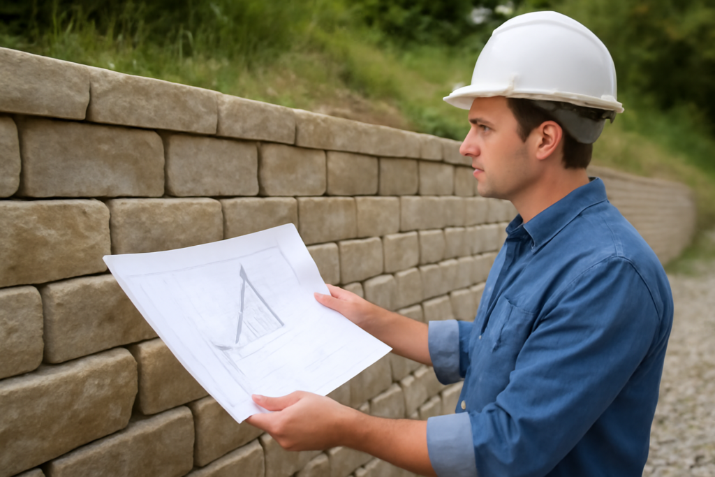
Most retaining walls don’t fail because someone stacked block badly. They fail because of decisions made before the first course was set: a driveway parked too close behind the wall, a face built dead plumb, no path for water to escape. Good retaining wall design is the discipline of accounting for three forces — surcharge loads, the wall’s geometry (batter), and water — before choosing materials at all. This is not an installation how-to; it’s the design layer underneath every install: how soil actually pushes on a wall, the three failure causes and the design answer to each, the height and permit thresholds that trigger professional engineering, and what an engineer does that a product brochure can’t.
What a Retaining Wall Actually Resists
Soil behind a wall behaves like a very heavy, very slow fluid. It exerts lateral earth pressure that increases with depth — which is why pressure diagrams are triangles, and why doubling a wall’s height roughly quadruples the total force it must resist. Three numbers govern the load:
- Soil unit weight: typically 110–130 lb per cubic foot.
- Internal friction angle: how well the soil holds itself up — clean gravel (~38°) pushes far less than saturated clay (~20° or worse). Clay is the villain of residential walls: heavy, weak, and water-holding.
- Active pressure coefficient (Ka): derived from the friction angle, usually 0.25–0.5 for residential soils. A 4-foot wall retaining average soil sees on the order of 250–400 lb of lateral force per linear foot; an 8-foot wall sees 1,000–1,600 lb — plus whatever water and surcharge add.
A wall can fail four ways: sliding (pushed forward off its base), overturning (rotating about its toe), bearing failure (crushing/settling into soft soil under the toe), and global failure (the entire slope, wall included, slips along a deep arc). Engineers check all four; DIY rules of thumb only cover the first two — one reason tall walls need stamps.
Failure Cause #1: Surcharge
A surcharge is any load sitting on the soil the wall retains — and it’s the most commonly ignored design input in residential work. Every pound on the surface within roughly a 45° line rising back from the wall base adds lateral pressure to the wall:
- Driveways and parked cars: code treats vehicular areas as at least 250 lb/sq ft of surcharge. A car parked 3 feet behind a 4-foot garden wall roughly doubles the design load.
- Buildings and footings: a shed, garage, or house footing bearing within the wall’s influence zone transfers structural load into the wall. This always requires engineering — see also our concrete foundation guide for how footing loads spread.
- Slopes above the wall: a backslope rising behind the wall is a continuous surcharge. A 3:1 slope above a wall can add 30–50% to design pressure; a 2:1 slope more.
- Another wall above (tiered walls): the upper wall surcharges the lower unless it’s set back at least twice the lower wall’s height. Closer than that, the tiers act as one tall wall and must be engineered as one — the classic DIY trap.
Design answer: keep loads out of the influence zone where you can (park the driveway back, set tiers apart), and where you can’t, size the wall for the surcharge — deeper blocks, geogrid reinforcement, or a structural stem wall. “It’s only 4 feet” stops being true the day a truck parks above it.
Failure Cause #2: Geometry — Batter, Embedment, and Base
Batter is the wall’s backward lean into the retained soil, and it’s free stability: leaning the resultant force path back toward the heel dramatically improves overturning resistance. Design norms:
- Segmental block systems build in batter via lips or pins — typically 3° to 8° (roughly 3/4 to 1.5 inches of setback per foot of height). Never defeat it by stacking plumb.
- Gravity walls (gabion, boulder, timber) want 1–2 inches of setback per foot minimum.
- Embedment: bury the base — rule of thumb one-tenth of wall height, minimum 4–6 inches below grade plus a compacted gravel leveling pad 6 inches thick. The buried toe resists sliding and protects against frost and erosion undermining.
- Base width: gravity walls need base depth (front-to-back) of roughly 50–60% of height. Reinforced segmental walls replace mass with geogrid — polymer mesh layers extending back into the compacted backfill, typically 60–100% of wall height in length, every 2–3 courses. Geogrid turns the soil mass itself into the wall; it’s how 20-foot block walls exist.
Failure Cause #3: Water
Hydrostatic pressure is the top killer of built walls. Saturated backfill nearly doubles the lateral load — water pressure (62.4 lb/cu ft acting fully laterally) piles on top of soil pressure, and freezing backfill adds ice lensing on top of that. Almost every leaning, bulging wall you’ve seen is a drainage failure wearing a masonry costume. The design package every solid wall gets:
- Free-draining backfill: a column of clean, angular 3/4-inch gravel at least 12 inches thick directly behind the full height of the wall — never native clay shoved back against the block.
- Geotextile separation fabric between gravel and native soil so fines don’t clog the drainage column.
- A collection pipe: 4-inch perforated drain at the heel, sloped 1% minimum, daylighting beyond the wall ends or into a storm system — not buried to nowhere.
- Weeps through solid walls (poured concrete, mortared masonry) every 6–8 feet as a backup path.
- Surface water management: grade the top of the wall to shed water away, and never point a downspout at the backfill zone.
Segmental block drains between units and gabions drain everywhere, but both still need the gravel column and fabric; poured concrete walls and mortared stone depend entirely on the drainage package and also need waterproofing on the soil face. In freeze climates, the drainage column doubles as frost protection — saturated backfill that freezes will move any wall ever built. Joint and crack behavior in the concrete itself follows the same logic covered in our concrete expansion joint guide.
Height and Permit Thresholds
| Wall height (bottom of footing to top) | Typical US requirement |
|---|---|
| Under 3 ft | Usually exempt; follow manufacturer tables |
| 3–4 ft | Often exempt if no surcharge; some cities require permits at 3 ft |
| Over 4 ft | Building permit + engineered (stamped) design in most jurisdictions — IRC/IBC baseline |
| Any height with surcharge | Permit + engineering (the exemption is void once a driveway, structure, or slope loads the wall) |
| Tiered walls closer than 2× lower wall height | Engineered as a single wall system |
Note the measurement: most codes measure from the bottom of the footing, not finished grade — a “4-foot” exposed wall with a foot of embedment is a 5-foot wall to the inspector. Local amendments vary widely; a call to the building department before design is step zero.
When You Need an Engineer — and What You Get
Hire a geotechnical or structural engineer when any of these is true: the wall exceeds 4 feet, carries any surcharge, retains clay or fill soils, sits above or below a structure, tiers with another wall, shows global-slope concerns (springs, previous slides, creek banks), or replaces a wall that already failed once. Expect $500–$2,000 for a stamped residential design — trivial insurance against a rebuild that can run $50–$100 per square foot plus excavation of a collapsed slope.
The engineer delivers what rules of thumb can’t: soil verification (sometimes with borings), factored checks on sliding, overturning, bearing, and global stability, a geogrid or footing schedule, drainage detailing, and a stamped drawing your permit office will accept — which also matters at resale and with insurers after any movement.
Design Checklist Before You Build
- Measured total height including embedment — which side of the 4-foot line are you on?
- Every surcharge inventoried: driveway, slope, shed, future pool deck, tier above.
- Soil identified: gravel/sand (friendly), silt (mediocre), clay or uncompacted fill (engineer territory).
- Batter specified and base/geogrid sized per the system’s engineering tables.
- Full drainage package drawn: gravel column, fabric, pipe, daylight outlet, surface grading.
- Permit question answered in writing from your jurisdiction.
- Utilities located (811) before any excavation.
FAQ
What is the most common cause of retaining wall failure?
Water — saturated backfill creating hydrostatic pressure the wall was never sized for. Surcharge loads added after construction are second; missing batter and undersized bases third.
Do I really need an engineer for a 5-foot wall?
In most US jurisdictions, legally yes (over 4 feet triggers stamped design), and practically also yes: at 5 feet the force per foot is roughly 60% higher than at 4 feet, and failure consequences shift from cosmetic to dangerous.
How far should a driveway be from a retaining wall?
Outside the wall’s influence zone — conservatively, a horizontal distance equal to the wall height. Closer than that, design the wall for a 250 lb/sq ft vehicular surcharge.
What batter should a retaining wall have?
Segmental systems: the built-in 3–8°. Gravity walls: at least 1 inch of setback per foot of height, 2 inches for timber and boulder walls. Plumb walls belong only on engineered cantilever designs with footings sized for it.