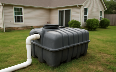
If your house runs on a private system instead of city sewer, a septic tank diagram is the fastest way to understand where your wastewater actually goes. Picture two connected parts buried in the yard: a watertight tank that separates solids from liquid, and a drain field that returns the treated liquid to the soil. Once you can see how those pieces line up, maintenance stops feeling like a mystery.
I’ve dug up, pumped, and repaired enough of these systems to tell you that most failures come from people not knowing what’s under the grass. So let’s walk the whole path, tank to soil, and mark the parts that matter.
- Septic Tank Diagram: The Basic Layout of a Septic System
- Reading the Tank Itself
- Baffles and Tees: The Unsung Parts
- How Wastewater Moves Through the System
- The Drain Field in Detail
- Where the Access Points Are
- What Goes Wrong and What the Diagram Tells You
- Gravity Systems vs. Pump Systems
- Mound and Alternative Systems
- Keeping the Whole System Healthy
Septic Tank Diagram: The Basic Layout of a Septic System
Every conventional gravity system has four zones lined up in a row, sloping slightly downhill:
- The house drain (building sewer): a 4-inch pipe that carries everything from toilets, sinks, and the washer out of the foundation.
- The septic tank: a buried 1,000- to 1,500-gallon watertight box where solids settle and bacteria start digesting waste.
- The distribution box (D-box): a small junction that splits the outgoing liquid evenly among the drain-field lines.
- The drain field (leach field): a set of perforated pipes in gravel trenches where liquid soaks into the soil and finishes treating.
The pipe leaving the house sits higher than the tank inlet, and the tank outlet sits higher than the field, so gravity moves water without a pump on most lots. Flat or low properties add a pump chamber, but the flow order stays the same.
Reading the Tank Itself
Look at a cutaway of the tank and you’ll see it split into two chambers by a partition wall with a hole near the middle. Wastewater enters the first chamber through the inlet pipe, and this is where the magic separation happens.
Three distinct layers form inside:
- Scum layer (top): grease, oils, soap, and anything that floats. It can build 4 to 8 inches thick before it needs pumping.
- Effluent (middle): the relatively clear liquid, sometimes called gray water zone. Only this layer is supposed to leave the tank.
- Sludge layer (bottom): the heavy solids that sink. When sludge reaches roughly one-third of the tank’s depth, it’s pumping time.
The two-chamber design gives solids a second chance to settle before the liquid moves on. That’s why a modern tank protects the drain field better than the old single-compartment tanks from the 1970s.
Baffles and Tees: The Unsung Parts
On the diagram, notice the T-shaped fittings at the inlet and outlet. These are the inlet and outlet baffles, and they do more work than their size suggests.
The inlet baffle directs incoming flow downward so it doesn’t stir up the scum layer or shoot straight across to the outlet. The outlet baffle pulls liquid from the middle of the tank, keeping scum from floating out and sludge from being sucked into the field. Many modern outlets also carry an effluent filter, a screened cartridge you can pull and rinse that catches stray solids before they clog the leach lines. If your system has one, hose it off once a year.
When a baffle rots off (common on old steel or concrete tanks), solids escape to the field and destroy it. A cracked or missing outlet baffle is one of the most expensive small failures in the whole system.
How Wastewater Moves Through the System
Follow the arrows on the diagram and the process is simple:
- Water leaves the house and enters the tank’s first chamber.
- Solids sink, grease floats, and bacteria begin breaking down the sludge.
- Clarified liquid passes through the partition into the second chamber for more settling.
- Effluent exits through the outlet baffle to the distribution box.
- The D-box splits flow among two to five trenches so no single line gets overloaded.
- Liquid trickles out of the perforated pipes, through 12 inches or so of gravel, and into the native soil, where microbes finish treatment before it reaches groundwater.
Nothing here is powered or complicated. The system’s job is simply to slow water down long enough for gravity and bacteria to do the treating.
The Drain Field in Detail
The leach field is the part homeowners understand least and damage most. Each trench holds a perforated pipe sitting on a bed of washed stone, wrapped in filter fabric, then buried under 6 to 12 inches of soil. The holes point down so effluent drips into the gravel and spreads across the trench bottom.
The soil beneath is the real filter. A layer called the biomat, a thin dark film of bacteria, forms at the trench-soil interface and does the final cleaning. A healthy biomat is good; a smothered, saturated one means the field can no longer absorb water, and that’s what people mean when they say a field has “failed.”
Keep vehicles, sheds, and deep-rooted trees off the field. Compaction and roots are the two fastest ways to kill it, and a replacement field runs $5,000 to $20,000.
Where the Access Points Are
A useful septic tank diagram marks the lids. Older tanks have two 12-inch inspection ports over the inlet and outlet, often buried under a foot of dirt. Newer installs bring risers with green or black lids up to grade so a pumper can reach them without digging.
If you don’t know where your lids are, probe with a metal rod about 10 to 15 feet out from where the sewer leaves the house, or pull the “as-built” drawing from your county health department. Installing risers costs $300 to $600 and pays for itself the first time you need service.
What Goes Wrong and What the Diagram Tells You
Once you can read the layout, troubleshooting gets logical:
- Slow drains everywhere, gurgling toilets: the tank is full of solids or the outlet is blocked. Check sludge depth first.
- Soggy, smelly ground over the field: effluent isn’t absorbing. The field is failing or overloaded.
- Sewage backing up into the house: blockage between the house and tank, or a completely full tank.
- Lush green stripe over the trenches: effluent is surfacing early, an early warning of a tired field.
Match the symptom to the section of the diagram and you’ll know whether to call a pumper or a repair contractor.
Gravity Systems vs. Pump Systems
Not every diagram looks the same, because the layout depends on your lot. A gravity system is the simplest: the house sits higher than the tank, and the tank higher than the field, so water flows downhill on its own with no moving parts. That’s the arrangement most of this guide describes, and it’s the cheapest to build and maintain.
On flat, low, or high-water-table lots, the diagram adds a pump chamber after the tank. Effluent collects in a second tank with a submersible effluent pump and a float switch. When the level rises, the pump kicks on and pushes liquid uphill to the drain field or a mound. These systems cost more, use electricity, and add a failure point, since a burned-out pump backs the whole system up. If your diagram shows a pump chamber and an alarm float, add “test the alarm” to your maintenance list.
Mound and Alternative Systems
Where soil drains poorly or the water table sits high, code often requires a mound system instead of a conventional buried field. On the diagram, the drain field is raised into an engineered sand-and-gravel mound above the natural grade, with a pump feeding it. Aerobic treatment units (ATUs) add air to speed up bacterial digestion and are common where lots are tight or soil is marginal. These variations all share the same first stage, a septic tank that separates solids, so the tank portion of the diagram stays familiar even when the disposal method changes. Knowing which type you have tells you what to inspect and how much service will cost.
Keeping the Whole System Healthy
The diagram makes the maintenance rules obvious. Pump the tank every 3 to 5 years for a family of four to keep sludge and scum from reaching the outlet baffle. Spread out laundry loads so you don’t flood the tank in one afternoon. Keep grease, wipes, paper towels, and harsh chemicals out, since they clog the tank and kill the bacteria doing your treatment for free.
A septic tank diagram isn’t just a technical drawing. It’s a map of a living system in your yard, and knowing how each part connects is the difference between a $400 pump-out and a $15,000 rebuild. Learn the flow once, respect the field, and a well-built system will run quietly for 25 to 30 years.